مشخصات FPR4K-NM-6X10SR-F
پارت نامبر FPR4K-NM-6X10SR-F متعلق به ماژولی از سری Cisco Firepower 4000 است که برای افزایش قابلیتهای شبکهای این دستگاهها طراحی شده است. در اینجا به توضیح جزئیات و ویژگیهای این ماژول میپردازیم:
مشخصات ماژول FPR4K-NM-6X10SR-F
1. **نوع ماژول**:
– ماژول شبکهای (Network Module) برای دستگاههای سری Firepower 4000.
2. **پورتها**:
– شامل 6 پورت 10 گیگابیتی SFP+ (10GbE SFP+ Ports) برای اتصال به شبکههای پرسرعت.
3. **نوع اتصال**:
– **SR (Short Reach)**: این ماژول به گونهای طراحی شده که با استفاده از فیبر نوری کوتاه برد (Short Reach) قادر به انتقال دادهها تا فاصلههای کوتاه (معمولاً تا 300 متر) میباشد.
4. **کاربردها**:
– **افزایش ظرفیت و انعطافپذیری شبکه**: با اضافه کردن این ماژول به دستگاههای سری Firepower 4000، میتوان تعداد و نوع اتصالات شبکه را افزایش داد و از سرعتهای بالاتر در انتقال دادهها بهرهمند شد.
– **بهبود عملکرد شبکه**: مناسب برای محیطهایی که نیاز به پهنای باند بالا و اتصالات سریع دارند، مانند دیتاسنترها، شبکههای بزرگ سازمانی، و محیطهای پر ترافیک.
5. **سازگاری**:
– این ماژول با دستگاههای سری Firepower 4000 سازگار است و به راحتی قابل نصب و راهاندازی میباشد.
مزایا FPR4K-NM-6X10SR-F
– **انعطافپذیری بالا**: با استفاده از پورتهای 10 گیگابیتی، امکان اتصال دستگاههای متعدد با سرعت بالا فراهم میشود.
– **قابلیت اطمینان**: طراحی شده برای کار در محیطهای حساس و حیاتی با نیاز به اتصالات پایدار و پرسرعت.
– **سهولت در استفاده**: نصب و راهاندازی آسان با کمترین نیاز به تنظیمات پیچیده.
نتیجهگیری
ماژول **FPR4K-NM-6X10SR-F** یکی از بهترین گزینهها برای ارتقاء دستگاههای Cisco Firepower 4000 است، به ویژه در محیطهایی که نیاز به پهنای باند بالا و اتصالات سریع و مطمئن دارند. با استفاده از این ماژول، میتوانید ظرفیت و کارایی شبکه خود را به میزان قابل توجهی افزایش دهید.
تماس برای مشاوره و خرید
برای دریافت مشاوره رایگان و اطلاعات بیشتر در مورد خرید این ماژول، با شرکت مهندسی داریا سرور تماس بگیرید. تیم متخصصین این شرکت آماده ارائه راهنماییهای لازم و تامین تجهیزات مورد نیاز شما هستند.
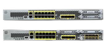
The following figure shows the Firepower 4100 series security appliance.

The following table lists the features for the Firepower 4100 series.
|
Feature |
4110 |
4120 |
4140 |
4150 |
||||||||
|---|---|---|---|---|---|---|---|---|---|---|---|---|
|
Form factor |
1 RU Fits a standard 19-inch (48.3cm) square-hole rack |
|||||||||||
|
Rack mount |
Slide rails, mount ears, and screws included 4-post Electronic Industries Association (EIA)-310-D rack |
|||||||||||
|
Airflow |
Front to rear Cold aisle to hot aisle |
|||||||||||
|
Processor |
Single 12-core |
Single 18-core |
Single 22-core |
|||||||||
|
Memory |
64-GB DDR4 DRAM |
128-GB DDR4 DRAM |
256-GB DDR4 DRAM |
256-GB DDR4 DRAM |
||||||||
|
Maximum number of interfaces |
24 With two 8-port network modules installed |
|||||||||||
|
Management port |
One Gigabit Ethernet Supports 1-Gb fiber or copper small form-factor pluggable (SFP) |
|||||||||||
|
Serial port |
One RJ-45 console |
|||||||||||
|
USB port |
One USB 2.0 Type A |
|||||||||||
|
Network ports |
Eight fixed 1-Gb and 10-Gb SFP+ ports (named Ethernet 1/1 through 1/8) |
|||||||||||
|
Small form-factor pluggable (SFP) ports |
Eight fixed 1-Gb and 10-Gb SFP+ ports See Supported SFP/SFP+ and QSFP Transceivers for a list of supported transceivers. |
|||||||||||
|
Pullout asset card |
Displays the serial number; on the front panel |
|||||||||||
|
Grounding lug |
On rear panel |
|||||||||||
|
Locator beacon |
On front panel |
|||||||||||
|
Power switch |
On rear panel |
|||||||||||
|
Network modules |
Two network module slots (named network module 2 and network module 3) |
|||||||||||
|
Supported network modules |
|
|||||||||||
|
AC power supply |
Two (1+1) power supply module slots Ships with one 400-W AC power supply modules Hot-swappable |
Two (1+1) power supply module slots Ships with two 400-W AC power supply modules Hot-swappable |
||||||||||
|
DC power supply |
Optional |
|||||||||||
|
Redundant power |
1+1 |
|||||||||||
|
Fan |
Six fan module slots 3+1 redundancy Hot-swappable |
|||||||||||
|
Storage |
Two SSD slots Ships with one 200-GB SSD installed in slot 1. Slot 1 is the primary SSD and should always be present. Slot 1 is reserved for the logical device application instance (threat defense or ASA).
|
Two SSD slots Ships with one 400-GB SSD installed in slot 1. Slot 1 is the primary SSD and should always be present. Slot 1 is reserved for the logical device application instance (threat defense or ASA).
|
||||||||||
|
MSP |
Installed in the second SSD slot only |
|||||||||||
|
Security standards certifications |
|
|||||||||||
|
Network Equipment Building Systems (NEBS) certification |
— |
Certified |
— |
— |
||||||||
روشهای پیادهسازی Cisco Firepower 4100
سری Cisco Firepower 4100 میتواند در مکانها و سناریوهای مختلفی پیادهسازی شود که برخی از نمونههای آن به شرح زیر است:
1. **در مراکز داده با استفاده از NGFW و ASA**:
– استفاده از قابلیتهای فایروال نسل جدید (Next-Generation Firewall) و نرمافزار ASA برای تامین امنیت پیشرفته در مراکز داده.
2. **در لایه هسته/تجمیع (Aggregation) یک مرکز داده سهلایه با پیکربندی با دسترسی بالا (High Availability)**:
– به کارگیری در لایههای مرکزی و تجمیع یک مرکز داده سهلایه برای اطمینان از دسترسی بالا و پایداری سرویسهای امنیتی.
3. **به عنوان یک سرویس امنیتی چندمنظوره در زیرساختهای همگرا (Converged Infrastructure)**:
– استفاده در زیرساختهای همگرا مانند vBlock و FlexPod در لایه دسترسی برای ارائه سرویسهای امنیتی چندمنظوره.
4. **به عنوان یک دستگاه امنیتی پرسرعت در مراکز داده بین لبه WAN و هسته مرکز داده با پیکربندی با دسترسی بالا**:
– پیادهسازی در مکانهای حیاتی بین لبه شبکه WAN و هسته مرکز داده برای اطمینان از امنیت و کارایی بالا.
5. **پیادهسازی کلاسترهای بین مراکز داده (Inter-DC Clustering)**:
– استفاده در کلاسترهای امنیتی بین مراکز داده مختلف برای ایجاد یک محیط امنیتی هماهنگ و متمرکز.
6. **در طراحیهای جدید مرکز داده با معماری اسپاین/لیف (Spine/Leaf)**:
– پیادهسازی به عنوان یک لیف (Leaf) که به طور اختصاصی وظایف امنیتی را ارائه میدهد.
محتوای بسته FPR4K-NM-6X10SR-F
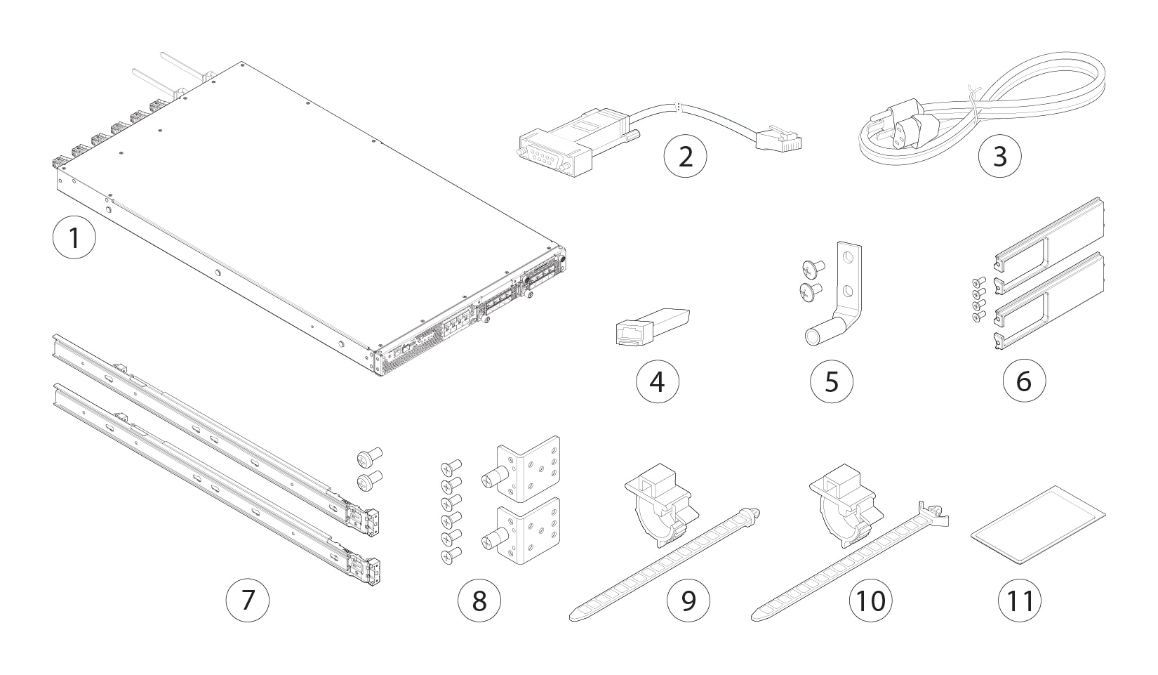
شکل زیر محتوای بستهبندی برای دستگاه Firepower 4100 را نشان میدهد. توجه داشته باشید که محتویات بسته ممکن است تغییر کنند و بسته شما ممکن است شامل اقلام اضافی یا کمتری باشد.
در این بخش، اقلام معمولی که ممکن است در بستهبندی دستگاه Firepower 4100 یافت شوند عبارتند از:
– **دستگاه Firepower 4100**: دستگاه اصلی که شامل سختافزار و نرمافزار مورد نیاز برای ارائه خدمات امنیتی است.
– **کابلهای اتصال**: شامل کابلهای برق، شبکه، و سایر اتصالات ضروری.
– **دفترچه راهنما**: شامل دستورالعملهای نصب و راهاندازی و راهنمای کاربر.
– **کیس و رک مانتینگ**: تجهیزات مورد نیاز برای نصب دستگاه در رکهای استاندارد دیتاسنتر.
– **ماژولهای اضافی**: ممکن است شامل ماژولهای افزایشی برای بهبود قابلیتها و ظرفیت دستگاه باشد.
نتیجهگیری
سری Cisco Firepower 4100 با قابلیتهای پیشرفته و انعطافپذیری در پیادهسازی، یک انتخاب ایدهآل برای مراکز داده و سازمانهای بزرگ است که نیاز به امنیت چندلایه و کارآمد دارند. محتوای بستهبندی این دستگاه ممکن است بسته به نیازهای خاص شما و پیکربندیهای انتخابی متفاوت باشد، بنابراین توصیه میشود همیشه دستورالعملهای سازنده را بررسی کنید و با تامینکننده محصول خود مشورت کنید تا از کامل بودن بستهبندی و اقلام موجود اطمینان حاصل کنید.

|
1 |
Firepower 4100 chassis |
2 |
Blue console cable PC terminal adapter (part number 72-3383-01) |
|
3 |
Two power cords (country-specific) See Power Cord Specifications for a list of supported power cords. |
4 |
10/100/1000BASE-T SFP transceiver |
|
5 |
Ground lug kit (part number 69-1000359-01):
|
6 |
Cable management bracket kit (part number 69-100376-01)
|
|
7 |
Two slide rails with two M3 x 0.5 x 6-mm screws (48-101144-01) |
8 |
Two slide rail locking brackets (part number 700-105350-02) Six 8-32 x 0.375-inch Phillips screws (part number 48-2696-01) |
|
9 |
Artesyn tie wrap and tie wrap clamp (part number 52-100204-01) |
10 |
Flextronics tie wrap and tie wrap clamp (part number 52-100202-01) |
|
11 |
Cisco Secure Firepower 4100 This document has a URL and QR code that point to the Digital Documentation Portal. The portal contains links to the Product Information page, the Hardware Installation Guide, the Regulatory and Safety Information Guide, the Getting Started Guide, and the Easy Deployment Guide. |
— |
Serial Number Location
The serial number for the Firepower 4100 series chassis is located on the pullout asset card on the front panel.

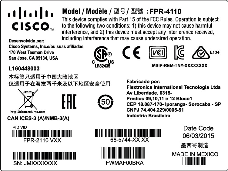
You can also view additional model information on the compliance label located on the bottom of the chassis.

Front Panel
The following figure shows the front panel of the Firepower 4100.

|
1 |
RJ-45 console port |
2 |
Gigabit Ethernet management port |
||
|
3 |
USB 2.0 Type A port |
4 |
Eight fixed SFP+ (1-Gb/10-Gb) ports (in network module slot 1) Ethernet 1/1 through 1/8 labeled top to bottom, left to right |
||
|
5 |
SSD 1 Reserved for the primary SSD; slot 1 must always be populated. |
6 |
SSD 2 Reserved for the optional MSP. |
||
|
7 |
Power LED |
8 |
Locator LED |
||
|
9 |
Pullout asset card |
10 |
Network module 2
|
||
|
11 |
Network module 3
|
- RJ-45 Console Port
-
The Firepower 4100 has a standard RJ-45 console port. You can use the CLI to configure your Firepower 4100 through the RJ-45 serial console port by using a terminal server or a terminal emulation program on a computer.
The RJ-45 (8P8C) port supports RS-232 signaling to an internal UART controller. The console port does not have any hardware flow control, and does not support a remote dial-in modem. The baud rate is 9600. You can use the standard cable found in your accessory kit to convert the RJ-45 to DB-9 if necessary.
- Type A USB Port
-
You can use the external USB Type A port to attach a data storage device. The external USB drive identifier is
disk1:. The USB Type A port supports the following:-
Hot swapping
-
USB drive formatted with FAT32
-
Boot kick-start image from the Supervisor ROMMON for discovery recovery purposes
-
Copy files to and from workspace:/ and volatile:/ within local-mgmt. The most relevant files are:
-
Core files
-
Ethanalyzer packet captures
-
Tech-support files
-
Security module log files
-
-
Platform bundle image upload using download image usbA:
The USB Type A port does not support Cisco Secure Package (CSP) image upload.
-
- Network Ports
-
The Firepower 4100 chassis has eight fixed ports that require 1-Gb/10-Gb SFP/SFP+ transceivers (fiber or copper). They are numbered from left to right starting with 1 and are named Ethernet 1/1 through Ethernet 1/8. The 4100 also has two network module slots that support different numbers of ports depending on the network module. See Network Modules for the supported network modules. See for Supported SFP/SFP+ and QSFP Transceivers the list of supported transceivers.
Each port has LEDs that represent link/activity status.
- Management Port
-
The Firepower 4100 chassis has a management port that requires a 1-Gb fiber or copper SFP.
Front Panel LEDs
The following figure and table describe the Firepower 4100 front panel LEDs.

|
1 |
Management
|
2 |
Health (SYS)
|
|
3 |
SSD
|
4 |
Power
|
|
5 |
Active (ACT) This LED is not supported; reserved for future use. |
6 |
Locator LED
|
|
7 |
Network activity
|
Rear Panel
The following figure shows the rear panel of the Firepower 4100.

|
1 |
Power on/off switch |
2 |
Power supply module 1 |
||
|
3 |
Power supply module 2 |
4 |
Fan module 1 |
||
|
5 |
Fan module 2 |
6 |
Fan module 3 |
||
|
7 |
Fan module 4 |
8 |
Fan module 5 |
||
|
9 |
Fan module 6 |
10 |
Location for the two-post grounding lug
|


Reviews
There are no reviews yet.